TL;DR:
- Millwork shop drawings detail how custom woodwork is built, from joinery to hardware fitting, to meet contract specifications. They differ from architectural drawings by focusing on fabrication intent, helping prevent costly errors and rework. Properly prepared, reviewed, and coordinated shop drawings ensure smooth project execution and accurate installation.
Millwork shop drawings are fabrication documents that specify exactly how custom woodwork is built, joined, installed, and hardware-fitted to meet contract requirements. Unlike architectural drawings, which communicate design intent, shop drawings communicate fabrication intent. That distinction matters on every project. Architects, builders, and contractors who understand this difference avoid the most common and costly coordination failures in custom millwork work. This explainer covers what these drawings contain, how they differ from design documents, and how to use them to keep projects on track.
What are millwork shop drawings?
A millwork shop drawing is a fabrication intent document that shows how work is built, joined, installed, and hardware-specified to align with contract documents. Architectural drawings tell you what a space should look like. Shop drawings tell the fabricator how to build it. That gap between design vision and production reality is exactly what shop drawings fill.

The Architectural Woodwork Institute (AWI) sets the documentation standards most fabricators and architects reference for woodwork submittals. Following AWI guidelines gives all parties a shared language for grades, tolerances, and finish expectations. Without that shared standard, even well-intentioned drawings create confusion at the shop floor.
Without accurate shop drawings, fabricators must guess assembly details, which causes material waste and products built out of spec. That is not a hypothetical risk. It is the most common source of millwork rework on commercial and residential projects alike.
What does a complete shop drawing set include?
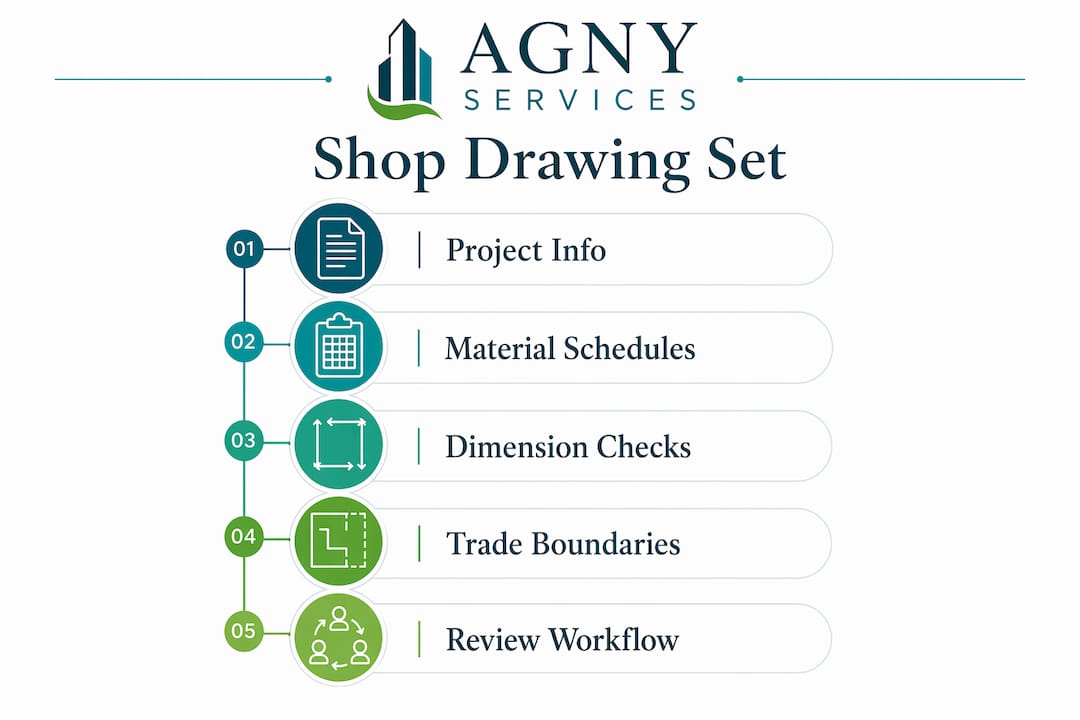
A complete set of millwork shop drawings follows a logical sequence from project context to room-level detail. A well-prepared package flows from project identification through elevations, sections, and material schedules to support clear review and accurate fabrication.
Project identification and revision tracking
Every drawing set opens with a cover sheet that lists the project name, address, architect of record, general contractor, fabricator, submittal date, and revision log. Revision tracking is not optional. When a drawing changes after approval, the log records who changed it, when, and why. That record protects every party if a dispute arises.
Drawing types in a standard set
Complete shop drawings cover plans, elevations, sections, details, cut lists, hardware schedules, and sometimes CNC-compatible machine-ready files. Each drawing type serves a specific purpose:
- Plans show the layout of millwork within a room, including overall dimensions and relationship to walls, windows, and adjacent trades.
- Elevations show the face of each cabinet, panel, or unit with height, width, door and drawer configuration, and hardware locations.
- Sections cut through the unit to reveal construction depth, shelf positions, back panel thickness, and joinery method.
- Details zoom in on specific connections, edge profiles, or hardware mounting conditions.
- Cut lists translate the drawing geometry into individual parts with dimensions, material species, and grain direction.
Material, hardware, and finish schedules
The schedule pages specify wood species, veneer grade, panel core type, hardware manufacturer and product code, and finish system. Vague descriptions like “stained wood” are not acceptable in a professional submittal. A proper schedule reads: “White oak, rift-sawn, AWI Grade 1, Rubio Monocoat Oil Plus 2C, color Pure.”
| Schedule type | What it specifies |
|---|---|
| Material schedule | Species, grade, core type, panel thickness |
| Hardware schedule | Manufacturer, product code, finish, quantity |
| Finish schedule | System, color, sheen level, application method |
| Installation notes | Blocking requirements, fastener type, clearances |
VIF stamps and scribe allowances
Critical dimensions such as wall-to-wall and floor-to-ceiling measurements are flagged with a “VIF” (Verify in Field) stamp, requiring physical measurement confirmation before fabrication starts. This protects the fabricator from building to a dimension that does not match the actual site condition. Scribe pieces of 3/4 to 1 inch give installers material to trim cabinetry edges to uneven walls or ceilings. Both tools reflect a core principle: good millwork drafting techniques account for real-world construction irregularities before the first board is cut.
How do shop drawings reduce coordination risk?
Shop drawings function as a shared coordination document among architects, general contractors, subcontractors, and fabricators. They cut miscommunication and project delays by giving every stakeholder a single reference for fabrication and installation instructions.
Defining trade boundaries
Clear trade boundaries in shop drawings specify which party handles each critical action. A typical millwork drawing will note: “Electrical contractor to provide power at this location prior to cabinet installation” or “Stone installer responsible for countertop cutout.” Without those notes, two trades arrive on the same day expecting the other to have done the prep work. That conflict costs time and money. Agny’s approach to trade coordination treats shop drawings as the primary tool for preventing exactly that scenario.
The review and approval workflow
The standard review cycle moves from fabricator to general contractor to architect. The architect’s review focuses on design intent conformance, not on validating the fabricator’s construction methods. Architects confirm compliance with the architectural vision and leave fabrication detail review to the fabricator. That division of responsibility is deliberate. Architects are not responsible for machine dimensions or joinery choices. Fabricators are.
The numbered steps below reflect the standard workflow on a well-run project:
- Fabricator receives approved architectural drawings and specifications.
- Fabricator prepares shop drawings internally and conducts a self-check before submission.
- Fabricator submits the drawing package to the general contractor.
- General contractor reviews for scope, coordination, and site conditions.
- General contractor forwards to the architect for design intent review.
- Architect returns drawings with one of three stamps: Approved, Approved as Noted, or Revise and Resubmit.
- Fabricator incorporates any required revisions before starting production.
Pro Tip: Submit drawings in a logical room-by-room sequence rather than by cabinet number. Reviewers think spatially, and a sequence that mirrors how they walk the space cuts review time significantly.
How do architectural drawings differ from shop drawings?
Architectural drawings and shop drawings serve different purposes and carry different responsibilities. Confusing the two is one of the most common errors project teams make.
Architectural drawings convey spatial layout, appearance, and design vision. They show where millwork sits in a room, what it looks like from the outside, and how it relates to the overall design. They do not show joinery, hardware placement, or material grades. Shop drawings provide those fabrication details. They fill the gap between what the architect drew and what the fabricator needs to build it correctly.
| Drawing type | Primary purpose | Prepared by | Reviewed by |
|---|---|---|---|
| Architectural drawing | Design intent, spatial layout | Architect | Owner, GC |
| Millwork shop drawing | Fabrication and installation detail | Fabricator | GC, then architect |
The millwork design documentation that architects produce sets the standard. Shop drawings then translate that standard into production instructions. Neither document replaces the other. A project that relies only on architectural drawings will produce millwork that fits the design concept but may not fit the actual space or meet the contract specifications for construction quality.
What are the best practices for preparing and reviewing shop drawings?
Quality shop drawings start with the fabricator’s internal process, not with the submittal itself. A drawing package that has not been checked internally before submission wastes the architect’s review time and delays the project.
Fabricator preparation checklist
Before submitting any package, fabricators should verify the following:
- All dimensions match the architectural drawings and any addenda issued after the original set.
- VIF stamps are applied to every dimension that requires field verification.
- Hardware product codes match the current specification, not a superseded version.
- Trade boundaries are clearly noted on every drawing where another contractor is involved.
- The revision log is current and all prior comments have been addressed.
What architects and GCs should verify
Quality control during shop drawing review requires checking design conformance, specification compliance, dimensional accuracy, trade coordination, and scope clarity. Architects should confirm that the design intent is preserved. General contractors should confirm that the scope matches the contract and that no work has been added or omitted without a change order.
Rushed or cursory reviews diminish the value of shop drawings and cause rework and project delays. An approval stamp without detailed verification of hardware, assembly, and interfaces is a professional failure. The drawing package is only as reliable as the rigor applied to reviewing it.
Pro Tip: When reviewing elevations, print them at a scale that matches the actual installation height. Errors in door swing clearance and hardware placement become obvious at full scale in a way they never do on a reduced-size PDF.
Digital tools and CAD-to-CAM workflows
Modern millwork drafting techniques increasingly use BIM-integrated workflows where the shop drawing model feeds directly into CNC cutting files. This CAD-to-CAM process reduces transcription errors between the drawing and the machine. Construction project management platforms that track submittal workflows also help teams manage revision cycles without losing track of which drawing version is current. The industry standards for millwork that govern these workflows are updated regularly, and staying current with AWI publications is part of professional practice.
Key Takeaways
Millwork shop drawings are the single most effective tool for aligning fabricators, architects, and contractors on custom woodwork projects, preventing rework before it starts.
| Point | Details |
|---|---|
| Fabrication intent is distinct | Shop drawings show how to build; architectural drawings show what to build. |
| Complete sets prevent guesswork | Plans, elevations, sections, schedules, and cut lists together eliminate fabricator assumptions. |
| VIF stamps protect all parties | Flag unverified dimensions before fabrication to avoid costly misfits on site. |
| Review rigor determines value | A cursory approval stamp undermines the entire shop drawing process. |
| Trade boundaries must be explicit | Naming responsible parties for each task in the drawing prevents mid-installation conflicts. |
Why I think most teams underestimate shop drawings
Most project teams treat shop drawings as a compliance step. They get submitted, they get stamped, and everyone moves on. That approach is where projects go wrong.
I have seen millwork arrive on site that was built to a drawing no one had actually read past the cover sheet. The hardware was wrong, the scribe allowance was missing, and the electrical rough-in was in the wrong location because the trade boundary note was buried on page 14. The rework cost more than the original fabrication.
The teams that get millwork right treat shop drawings as living production control documents. They mark them up. They hold coordination meetings around them. They use them to run the installation, not just to satisfy the submittal log. AWI standards give you the framework, but discipline in applying that framework is what separates a clean installation from a costly one. Architects who take their review seriously, and fabricators who submit complete packages, protect everyone’s margins and schedule. That is not idealism. It is the most practical thing you can do on a millwork project.
— Grzegorz
Agny’s millwork expertise for architects and contractors
Agny works with architects, builders, and contractors across New York on millwork projects where documentation quality directly affects the outcome. Whether you are coordinating a kitchen renovation or a full commercial millwork package, the gap between a good drawing set and a poor one shows up in the field.

Agny’s resources cover custom millwork investment decisions, fabrication coordination, and the millwork industry standards that govern professional submittals. If you are preparing or reviewing a millwork package and want a team that understands both the design and the production side, Agny is the right starting point.
FAQ
What is the difference between a shop drawing and an architectural drawing?
An architectural drawing shows design intent, including layout, appearance, and spatial relationships. A shop drawing shows fabrication intent, including joinery, hardware placement, material grades, and installation instructions.
What does VIF mean on a millwork shop drawing?
VIF stands for “Verify in Field.” It flags a dimension that must be physically measured on site before fabrication begins, protecting the fabricator from building to an inaccurate plan dimension.
Who is responsible for reviewing millwork shop drawings?
The fabricator submits drawings to the general contractor, who reviews for scope and site coordination. The architect then reviews for design intent conformance. Fabrication detail accuracy remains the fabricator’s responsibility throughout.
What happens if shop drawings are approved without a thorough review?
A cursory approval without verifying hardware, assembly, and trade interfaces leads to rework, installation conflicts, and project delays. The approval stamp does not transfer liability for fabrication errors to the reviewer.
How do shop drawings support millwork project planning?
Shop drawings align all stakeholders on dimensions, materials, hardware, and trade responsibilities before fabrication starts. That alignment reduces change orders, speeds installation, and protects the project schedule.