

TL;DR:
- Effective millwork design relies on precise documentation, accurate site measurements, and early coordination to prevent costly errors. Clear specifications of materials, fasteners, and finishes, along with thorough MEP alignment, ensure smooth installation and reliable results. Asking targeted questions early and using standard details significantly reduce fabrication mistakes and project delays.
Millwork design is the process of planning and detailing custom architectural woodwork elements that serve both aesthetic and functional roles in a building. A complete guide to millwork design covers everything from material selection and CAD documentation to shop drawing coordination and MEP integration. Architects, interior designers, and homeowners who master this process avoid costly fabrication errors, reduce rework, and deliver spaces where every wood element fits precisely. The difference between a smooth installation and a costly redo almost always traces back to documentation quality and early collaboration.
What are the essential tools and documentation for millwork design?
Millwork design requires three categories of resources: design tools, material knowledge, and formal documentation. Skipping any one of them creates gaps that surface during fabrication or installation.
Design tools and software
CAD software is the standard for producing millwork drawings. Programs like AutoCAD and Revit let designers draw every element to scale, which is critical because scaled drawings permit accurate integration of equipment and prevent last-minute adjustments. Line weights, dashed lines, and layered blocks in CAD drawings distinguish cut elements from adjacent features, making the drawings readable for fabricators. Physical tools, including laser measures and digital calipers, capture field dimensions that software cannot generate on its own.

Material selection
Wood species, finishes, and hardware each affect the final result in different ways. Profiles, grain matching, and finish specifications directly affect both aesthetics and durability. A designer who specifies white oak with a wire-brushed finish must document that choice explicitly, including sheen level and application method, so the fabricator produces the correct result without guessing.
Pro Tip: Start with existing standard details and modify them rather than drawing every millwork component from scratch. This approach cuts drawing time and reduces the chance of introducing new errors.
Required documentation
The core document set for any millwork project includes:
- Scaled plans showing overall layout and component placement
- Elevations depicting each face of a millwork unit at a consistent scale
- Sections with joinery details showing how parts connect
- Hardware schedules listing every hinge, pull, and slide with manufacturer references
- Finish schedules specifying material, color, sheen, and application notes
| Document type | Purpose |
|---|---|
| Scaled plan | Shows overall layout and component footprint |
| Elevation drawing | Depicts each face of a unit at a consistent scale |
| Section detail | Reveals joinery, thickness, and connection methods |
| Hardware schedule | Lists every hardware item with model and finish |
| Finish schedule | Specifies material, color, sheen, and application |
Millwork shop drawings must include all five document types to avoid costly fabrication errors. Missing even one creates ambiguity that fabricators resolve through guesswork, and guesswork produces wrong parts.
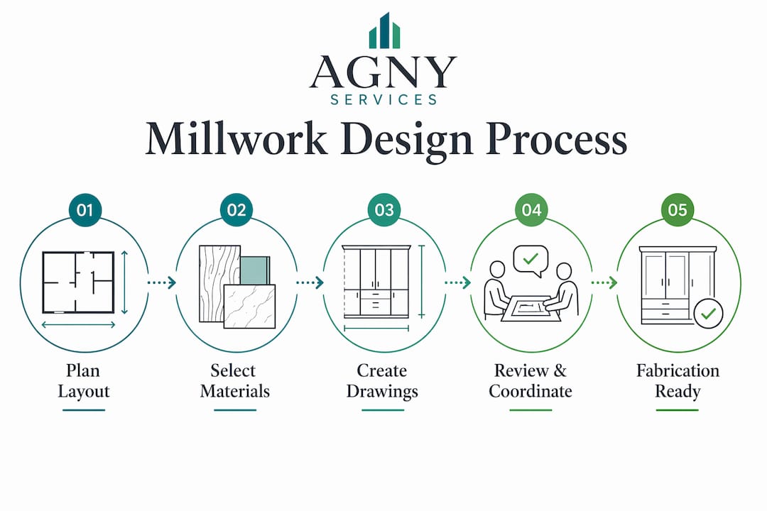
How do you execute millwork design from concept to fabrication-ready drawings?
A structured process separates projects that install cleanly from those that require expensive revisions. The eight phases below reflect best practices in millwork documentation.
- Review design intent. Confirm the aesthetic goals, functional requirements, and budget constraints with the project team before drawing anything.
- Conduct site analysis. Measure existing conditions, document wall plumb and floor level, and photograph every surface the millwork will contact.
- Create the overall layout. Draw the full plan view at a workable scale, placing each millwork unit in its correct position relative to walls, doors, and windows.
- Break down into components. Divide each unit into its parts: carcass, face frame, doors, drawers, shelves, and trim elements.
- Detail joinery and connections. Draw sections showing how parts join, including dado depths, rabbet widths, and fastener locations.
- Integrate hardware specifications. Add hardware to the drawings and schedule, noting mounting heights and clearance requirements for each item.
- Document finishes and materials. Complete the finish schedule with species, profile, grain direction, and sheen level for every visible surface.
- Coordinate with other trades. Cross-check drawings against MEP plans and confirm that outlet locations, plumbing rough-ins, and lighting positions align with the millwork layout.
Pro Tip: Treat the shop drawing phase as a collaborative RFI process. Ask targeted questions early about complex shapes, clearances, and material substitutions. Proactive questions cost nothing. Fabrication mistakes cost days.
The RFI step deserves special attention. Millwork shop drawings reflect a company’s professionalism and attention to detail, directly influencing fabrication efficiency and project timelines. A drawing set that forces fabricators to interpret unclear details will produce inconsistent results, even with skilled craftspeople.
What are common millwork design mistakes and how do you avoid them?
Most millwork failures trace back to a small set of recurring errors. Recognizing them early is the fastest way to protect your project.
Dimension inaccuracies
A single 1/2-inch measurement error can cost a full day of on-site labor and delay project completion by weeks. Field conditions rarely match architectural drawings exactly. Walls bow, floors slope, and corners are seldom truly square. Requesting accurate field dimensions before finalizing drawings reduces rework and delays significantly.
Vague design intent
The biggest misconception in millwork is that fabricators can interpret unclear design intent on their own. Explicit documentation eliminates misinterpretation and prevents painful review cycles. Designers must label toe kick materials, specify reveal dimensions, and call out every condition where two materials meet. Leaving these details open invites fabrication errors that are expensive to correct after the fact.
Common documentation gaps that cause problems:
- Unlabeled toe kick material or height
- Missing reveal dimensions between doors and face frames
- No callout for inside corner treatment
- Absent grain direction notes on visible panels
- Unspecified edge banding material or thickness
Misalignment with other trades
Inconsistencies between design drawings and shop drawings are a red flag that requires immediate coordination before fabrication proceeds. When a designer skips cross-checking millwork elevations against electrical plans, outlet boxes end up inside cabinet backs. Fixing that condition in the field means cutting holes in finished millwork, which damages the surface and weakens the structure.
Pro Tip: Request field dimensions at least two weeks before the shop drawing submission deadline. Verify that every shop drawing dimension corresponds 1:1 with your design drawings. Any discrepancy triggers an RFI, not a field fix.
How do you coordinate millwork design with MEP systems effectively?
MEP coordination is where millwork projects most often fail silently. The conflict does not appear until installation day, when a cabinet back lands directly over an electrical box.
Outlet and data port placement
Mounting heights for outlets and data ports must be clearly documented and coordinated with millwork elevations to prevent installation conflicts. A standard 18-inch outlet height works in open wall conditions but conflicts with a 36-inch base cabinet that has a 4-inch toe kick and a 32-inch carcass. The designer must show the outlet location on the millwork elevation and confirm clearance with the electrical plan.
Lighting and cable management
Undercabinet lighting requires a dedicated raceway or channel built into the millwork. Designers who specify LED strip lighting must show the channel depth, the wire exit point, and the switch or dimmer location on the elevation drawing. Missing any one of these details forces the electrician to improvise, which produces visible surface cuts or exposed conduit.
| Coordination condition | Coordinated outcome | Uncoordinated outcome |
|---|---|---|
| Outlet location | Shown on millwork elevation, confirmed with electrical plan | Box discovered behind cabinet back during installation |
| Undercabinet lighting | Channel and wire exit detailed in drawings | Exposed conduit or surface-mounted raceway added in field |
| Plumbing rough-in | Sink base drawn with accurate cutout and access panel | Cabinet back cut on site, weakening structure |
| Data port height | Noted on elevation and cross-checked with low-voltage plan | Port blocked by drawer or shelf |
Cross-checking elevations against both electrical and plumbing plans before submitting shop drawings catches the majority of these conflicts. The coordination of power and data requirements in scaled drawings is what makes viable layouts possible and prevents last-minute field adjustments.
Key Takeaways
Successful millwork design depends on explicit documentation, accurate field dimensions, and proactive coordination with fabricators and other trades before a single piece is cut.
| Point | Details |
|---|---|
| Documentation completeness | Every project needs scaled plans, elevations, sections, hardware schedules, and finish schedules. |
| Field dimensions first | Request accurate site measurements before finalizing drawings to prevent costly rework. |
| RFI as standard practice | Treat shop drawing review as a collaborative question-and-answer process, not a one-way submission. |
| MEP cross-check | Verify outlet, lighting, and plumbing locations against millwork elevations before fabrication begins. |
| Explicit labeling | Specify toe kicks, reveals, grain direction, and edge banding to eliminate fabricator guesswork. |
Why clarity separates good millwork from expensive mistakes
Every millwork project I have worked on that went sideways had the same root cause: someone assumed the other party understood what was intended. The fabricator assumed the designer meant standard reveal dimensions. The designer assumed the electrician had seen the millwork elevations. Neither assumption was checked, and the result was a cabinet back with an outlet box cut through it on installation day.
The custom millwork design process rewards people who ask obvious questions early. I have seen experienced designers hesitate to send an RFI because they thought the question made them look uninformed. That hesitation costs far more than the five minutes it takes to write the question. A fabricator who receives a clear, specific RFI respects the designer more, not less.
One practice I return to on every project is using existing standard details as a starting point. Modifying a proven detail is faster and safer than drawing from scratch. The quality control process for millwork is not about catching errors after the fact. It is about building a documentation system that makes errors unlikely in the first place. That shift in mindset, from reactive to preventive, is what separates projects that install in a day from those that drag on for weeks.
— Grzegorz
Agny’s millwork design expertise for your next project
Agny specializes in millwork design documentation, shop drawing coordination, and full-scale renovation projects across New York. Whether you are an architect managing a commercial fit-out or a homeowner planning a custom millwork installation, Agny’s team brings the technical depth and trade coordination experience to get your drawings fabrication-ready the first time.
Agny handles every phase from design intent review through MEP cross-checking and final finish documentation. Projects move faster when documentation is right from the start. Contact Agny to discuss your millwork scope and get a clear plan for delivering accurate, installation-ready drawings on schedule.
FAQ
What does a complete millwork drawing set include?
A complete set includes scaled plans, elevations, sections with joinery details, hardware schedules, and finish schedules. Missing any document type creates fabrication ambiguity that leads to costly errors.
How early should field dimensions be collected?
Field dimensions should be collected at least two weeks before the shop drawing submission deadline. Field irregularities as small as 1/2 inch can require full refabrication if caught too late.
What is an RFI in millwork design?
An RFI, or Request For Information, is a formal question sent to the designer or contractor when a drawing detail is unclear. Treating shop drawing review as an RFI process reduces expensive fabrication revisions.
How do you prevent outlet conflicts in millwork installations?
Show every outlet and data port mounting height on the millwork elevation drawing and cross-check it against the electrical plan. Missed outlet alignments are the most common MEP conflict in millwork projects.
What is the difference between custom and modular millwork?
Custom millwork is built to exact project dimensions and specifications, while modular millwork uses standardized components assembled on site. Custom millwork offers greater design flexibility but requires more detailed documentation and longer lead times.


